1. Involve Injection Molder Early & Design Part for Manufacturability
Design is one of the most important factors in avoiding part defects. It’s your earliest opportunity to avoid mistakes that can be costly both in regard to time and budget later on. Good design takes into account objectives including part function, aesthetic, manufacturability and assembly. Working with a knowledgeable design engineer and involving your injection molder early will help you find solutions to meet the needs of your specific part.
There are a number of important design elements to consider to ensure costly part mistakes are avoided:
Wall thickness:
Wall thickness is one of the most important factors with part design. The first rule of thumb is to determine the minimum wall thickness that will meet your design requirements. It is always good practice to work with your injection molder / design engineer to check thickness specifications for the material(s) you are considering for your part. Typical wall thickness ranges from .04 – .150 for most resins.
Important wall-thickness facts:
- Thinner walls require easier flowing plastics
- Longer flow lengths (distance from nozzle to the furthest corner of the part) may require thicker walls
Radius:
Sharp corners or angles can impede the flow of material. These abrupt transitions can cause the cavity to not fill or pack properly, creating a part with defects. Material flowing across a sharp corner creates stress in the plastic which can contribute to warp and dimensional instability.
Smooth corners that have a curve versus an angle are important in the injection molding process. The radius should be consistent on the inside and outside of the wall creating a uniform thickness. By incorporating this design element, the material will be able to flow through the cavity evenly.
Gate location:
The location where the molten plastic material flows into the mold part cavity called a gate. Every injection-molded part has at least one gate, and some have several gates. The placement of the gate can help ensure the cavity fills properly; however, it is best to have a uniform wall. Uniform wall thickness helps the mold fill and cool properly. In unavoidable situations, having a proper gate location can be a deciding factor in the success of a part. It is recommended that parts be designed with the gate in a location at which the melt enters the thickest section of the cavity to then flows out of a narrower region.
Draft:
Draft is an angle incorporated into the wall of a mold and the shape of the plastic part so the opening of the cavity is wider than its base. A plastic drinking cup is a good example of draft – it is smaller at the base than at the mouth so that the cup will come out of the mold. Draft is essential for injection molding.
Plastic heavily relies on mold draft in the removal of the part from the mold. When a part is designed without appropriate draft, removal of plastic parts is essentially impossible.
A design with sufficient draft is always considered to be a good practice. 1.5 degrees for a depth of 0.25mm is usually recommended by design engineers. General guidelines suggest that a draft angle of 0.5 degrees is recommended for core and 1.0 degree for cavity.
Surface textures also influence draft requirements. The more depth in a texture the more draft it requires. It is a good practice to determine the surface finish / texture requirements prior to starting you part design.
Ribs:
Ribs are used to help reinforce the overall part strength and support dimensional components of the design. Depending on the material used, ribs should be no greater than 2/3 of the wall thickness. Greater width could cause issues with the design and sinking may occur. To avoid this problem, a designer can often core out some material to reduce the shrinking. In addition, ribs cannot be too tall or too thin.
The height recommendations are generally no more than 3x the wall thickness. The corners should include radii and the height should include a draft (.5 to 1.5 degrees). The draft angle allows the part to be ejected from the mold.
Mold Flow Analysis:
When working with an experienced part designer and injection molder, mold flow analysis should be conducted before tooling production begins. Mold flow software can be used to evaluate the design to make sure it will produce the most consistent and highest quality parts from each cavity of the tool.
A virtual model of the mold is created and, using the known data and characteristics of the chosen material, the software is able to predict how the material will flow into the mold and its cavities. Different data points can be assessed, including pressure, fill time and melt temperature. Doing so allows for optimization of the process before tool production ever begins.
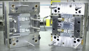
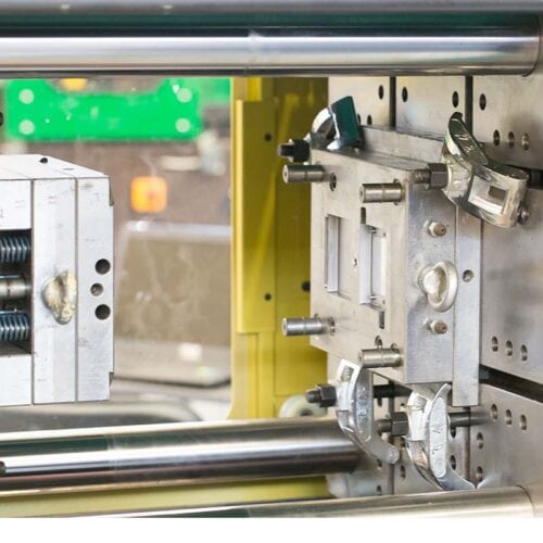
2. Don’t Skimp On Tool Design & Build
A perfect, defect-free part begins with the mold. Building the tool likely represents the largest investment in the manufacturing process; therefore, getting it right is critical to the success of a project. All of the design factors listed above are important considerations that can help you avoid costly mistakes. Additionally, the volume of parts required, as well as the material they will be made of will help drive how and with what materials to create the mold.
It’s important to keep in mind that more complex molds create a lot of intricate cavities that the plastic must flow through. Turns throughout the path in which the mold is filled can result in structural stresses and part cooling challenges. Designing a mold to have smooth turns can help with these stresses causing an issue for the part. Draft, as mentioned above, is not always compatible with a part’s design – both aesthetically and functionally. However, even a small amount of draft is preferred to no draft at all. Draft may vary with the surface finish or texture requirement of the part. For example, smoother tooling may require less draft.
Other part defects caused by mold design or maintenance issues include flash and short shots.
Flash:
Flash occurs when melted plastic escapes the mold cavity and appears as a wafer-like extension on a finished part. This defect occurs most often along the ejector pin parting line and is caused by excessive injection speed or pressure, too high of mold temperature and excessive barrel heat. Flash can occur due to poor mold design or neglected maintenance.
Short Shot:
A short shot occurs when resin falls short of filling the mold. It is often caused by gate blockages or too small of gate diameter. Short shot can also occur when the wrong resin type is used or improper process settings. Sometimes, the runner system needs to be redesigned to optimize flow.
3. Avoid Resin-Related Issues
Material Selection:
Choosing the best material can drive cost, functionality and versatility of your part. It is essential to work with a knowledgeable design engineer and injection molder to learn how different materials and their characteristics can optimize the production and life of your plastic part. Material selection is often based on the application of the part. Plastic requirements for a medical part may be significantly different than that of an aerospace application. Considerations like temperature, biological and chemical interaction, food or animal contact and more are all critical factors in material selection to avoid part defects.
Discoloration:
Discoloration is a defect that shows streaking or coloring in an injection-molded part. It usually occurs in one of two cases:
- Improper mixing of the masterbatch, the additive used for coloring material
- Impurities introduced to the material during the molding process
When a resin batch is not evenly mixed, you might see a streak of coloring in the end product. Additionally, you can have impurities introduced to a mold if the hopper, material feed area or mold plates of a machine are not cleaned properly prior to production. It is imperative that an injection molder clean the injection molding machine prior to producing parts.
Burn Marks:
Burn marks may appear as black or dark red discoloration when a material burns during the injection molding process and can be caused by one or more of the following:
- Overheating due to trapped air
- Excessive injection speed
- Excessive melt temperature
If burn marks occur, there are a few corrective actions a molder can take to avoid further defects.
Burn marks can be avoided by:
- Shortening the cycle time
- Lowering the temperature and/or slowing down the injection speed
- Trapped air can be avoided by ensuring adequate gas vents and gate sizes
Flow Lines:
Flow lines are streaks, patterns, or lines that are visible on a part. This defect is caused by the varying speed at which the molten plastic flows inside the mold tool. Flow lines may also occur as plastic flows through sections with varying wall thickness, or when the injection speed is too low causing the plastic to solidify at different speeds.
Flow lines can be avoided by:
- Increasing injection speeds and pressure to the optimal level
- Rounding corners and locations where the wall thickness changes to avoid sudden changes in direction and flow rate
Weld Lines:
Weld lines appear in a part where molten plastics meet each other as they flow from two different sections of the mold. This defect is caused by the inadequate bonding of two or more flow fronts when there is partial solidification of the molten plastic.
Weld lines can be avoided by:
- Raising the temperature of the mold or molten plastic
- Increasing the injection speed
- Adjusting the design for the flow pattern
- Switching to a plastic with a lower melting temperature
The majority of plastic part defects can be prevented by incorporating proper part and tooling design as well as material selection. The best way to avoid defects is to work with an experienced injection molder that understands the characteristics of various resins and their applications. Learn how Nicolet Plastics can help reduce part manufacturing lead times to get your product to market faster.